

Alison
-
Posts
501 -
Joined
-
Last visited
2 Followers

Recent Profile Visitors
10,197 profile views


Alison's Achievements
Advanced Member (3/3)
0
Reputation
-
Thomas, I just wanted to let you know that we have added a new feature to PetraSim v2024 based on you suggestions. We hope to release this later this month, but feel free to contact me if you would like to try out a beta version. The program will now allow the user to select the upper-most or lower-most exposed elements in a model. Best Regards, Alison
-
Print out of K-red and PER_MOD in (TOUGH3, PetraSim, ECO2N)
Alison replied to Prince Kumar's topic in TOUGH/PetraSim forum
For some reason, I'm not able to add an image. so here is the text that you can copy and paste into the OUTPU block: OUTPU----1----*----2----*----3----*----4----*----5----*----6 PETRASIM 4 SET 1 SET 2 ABSOLUTE 0 RELATIVE 0 -
Print out of K-red and PER_MOD in (TOUGH3, PetraSim, ECO2N)
Alison replied to Prince Kumar's topic in TOUGH/PetraSim forum
Prince, I am not sure that TOUGH3 is designed to output either of these parameters. I am about to output Absolute Permeability (which take into account the PMX value) and Relative Permeability using the OUTPU block displayed in the attached image. I would suggest that you contact LBL to see if its possible to output these other two parameters. Best Regards, Alison -
What do "X per m^2", etc in vector values in Result view mean?
Alison replied to Nori's topic in TOUGH/PetraSim forum
Hi Norihiro, Could you please send me your SIM File? I am not sure what this is, but think I can help after taking a look at the file and determining what simulator and output settings you are using. Best Regards, Alison alison@rockware.com -
Thanks for the update on this. It unfortunately seems that you may need to select these manually. If it would be appropriate for them to all be assigned the same material type, then this is a cell parameter that is selectable (right click on the material and choose "Select Visible Cells". Also, as you've found, if you assign a name to selected cells, they are listed under Named/Print cells. These are not "groupable", but you can selected multiple cells at once by holding down the Shift or Ctrl keys. I will pass your suggestions over to our programming team.
-
I think that you also might be trying to find these fields in the Borehole Manager, as they are hidden by default. In the Stratigraphy table, you can click the "Tab Manager" button to expose these. With the Stratigraphy table highlighted, click "Edit Fields". You can then check on the Dip and Dip Direction fields for the Top and Base contacts.
-
Thomas, This is a tricky problem because of the variable thickness of the elements in the Z direction. My only suggestion would be to right click on the internal boundary and click "Select Visible Cells". If this does not work with the current internal boundary, you might try creating one that is just below it to see if that works. If you continue to have problems, feel free to send us your SIM file and the TXT file used to create the internal boundary (to tech@rockware.com) and we'll experiment on our end. Best Regards, Alison
-
PetraSim v2016 is an older program that is no longer supported. I do recall an error such as this popping up many years ago. If you could contact us at tech@rockware.com with your licensing details, we will try to help you resolve the problem. Best Regards, Alison
-
Jackson, The RockWorks RwGrd and RwMod files do not allow for variable model spacing. RockWorks does include an option to create "Subsites" within a project, which are basically just a list of different project dimensions that are stored in the database and can be easily selected. Unfortunately, when a Stratigraphy model is created, the program stores the RwGrd files based on the stratigraphy units names and there is really no way to store multiple stratigraphy models in the same project. This is something we'll discuss internally. Your approach of creating a finer valley model and then extracting data for pseudo-boreholes for a larger scale model would work. There is a tool under the Grids menu for creating Stratigraphy data for pre-defined boreholes based on a list of RwGrd files (which could be the stratigraphy grids from your smaller scale valley model). Please take a look at the Grids | Grids -> Strat Data tool and let us know if you have any questions about how you would use this. Best Regards, Alison
-
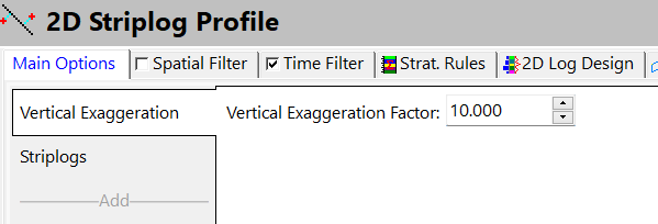
Bijoy, I do have one suggestion, it appears that you are adding the VE to your section after it is created. In most menus in RockWorks, there is an option to add a pre-determined vertical exaggeration. If you add this during the diagram creation, it should help with label and legend placement, scalebar tick mark sizes, etc.
-
CONVERGENCE FAILURE and STOP EXECUTION AFTER NEXT TIME STEP
Alison replied to Prince Kumar's topic in TOUGH/PetraSim forum
Prince, There seems to be a problem with element 1B11. I would suggest that you take a look at the location of that element relative to injection cells and also to the boundary between various phase states. Particularly with ECO2N (ECO2M also, I suspect), you can run into convergence problems at the boundary between, for example, injected CO2 gas and the aqueous phase. The solution to this is often related to changes to RP or CP curves. If you continue to have problems, please send your SIM file to tech@rockware.com and we'll take a look. Best Regards, Alison -
The different results between toughreact and petrasim2018
Alison replied to Merson's topic in TOUGH/PetraSim forum
PetraSim version 2018 includes executables for TOUGHREACT v1.2 that have been optimized to work with PetraSim. If your colleague is using a more recent version of TOUGHREACT, then this could explain the differences in results. I took a quick look at your model and the TOUGHREACT input files for the other simulation and noticed that your colleagues model contains 100 elements, while your model contains only 5. Its also possible that the difference in discretization could be causing these differences. Some other differences that I noticed: - RCOUR is set to 0.9 in your colleague's model (TOUGHREACT | Solution Parameters | Time and Convergence Tab), this will lead to smaller time steps, so you would need to increase the maximum number of times steps for your model or allows for an unlimited number of time steps. - KCPL is set to 2 in your colleague's model (TOUGHREACT | Solution Parameters | Advanced Tab) - Your colleague's model seems to be isothermal (Properties | Global Properties | EOS Tab) I would suggest that you experiment with these items more and contact tech@rockware.com if you need additional help. -
Don, The OBJ export was really developed with Sketchfab in mind, but I would expect that it would work in some other viewers as well. I tested this with some 3D PDF at one point and found that they really only worked with much smaller files. Sketchfab seems to be able to handle pretty large and complex files that the other programs could not handle. We are open to suggestions for new export formats, so please feel free to reach out to us with suggestions or to point us in the direction of a specific viewer you would like to work with. Best Regards, Alison
-
Jasmin, Please send us your RW3D file so we can try to reproduce the problem. You can send this to tech@rockware.com. Thanks, Alison
-
CONVERGENCE FAILURE and STOP EXECUTION AFTER NEXT TIME STEP
Alison replied to Prince Kumar's topic in TOUGH/PetraSim forum
Prince, Unfortunately, its very hard to determine what is causing this by looking at this log alone. Convergence problems like this are not uncommon in simulations where there are phase changes. Here are some very general suggestions: 1. You could try restarting your model by loading the SAVE file as initial conditions, and changing the RE1 (Relative Error Criterion) to a smaller value. 2. You could experiment with modifying your RP and CP curves. 3. If you are modeling as injection, you could try initializing your model with a very small amount of gas already present. If you continue to have problems, you are welcome to send your SIM file to tech@rockware.com and we'll see if we can provide additional suggestions. Thanks, Alison